High-End Audio Sound Reproduction Has Two Functions to Perform
 High end audio sound reproduction has two functions to perform. 1) Musicality and 2) Imaging. Here we are visiting the experience of stereo imaging.
A sonic image is a sound that is coming to us from some location. We expect the sonic image to be coming to us directly from the loudspeaker. Most often, the sound does seem to be coming from the speaker which means the sonic image is located on the speaker. We can look right at the speaker and see exactly where the sound is coming from, the speaker drivers. Sometimes it seems like we are sonically looking down the throat of the driver and with horn drivers, it’s especially true.
Head EffectsRoughly speaking, imaging is something we experience because we have 2 ears and a head. If sound comes from a speaker straight in front of us, both ears hear pretty much the same sound wave, at exactly the same time. If we turn our head to one side while the speaker is playing, it’s the same as looking ahead while moving the speaker around. The ear closest to the speaker hears a better sound. The other ear is in the acoustic shadow zone cast by our head and the sound is quieter. The acoustic image of the sound is located in the direction that seems the loudest. |
 |
| Also, this more distant ear hears the sound ever so slightly after the closer ear hears it. This difference in timing The timing of the wavefront as it crosses past the two ears influences our perception of where the sound comes from. Head shadowing as well. Both timing and head shadowing are wavelength dependent relative to the size of the head. |  |
| Directionality works for wavelengths less than 4x head diameter, 2 foot wavelength and shorter, 500 Hz (one octave above middle C4) and higher. Like everything else in audio there is an “imaging” frequency response curve. Essentially, we see images pretty well in the musical treble range, above C4, middle C or 250 Hz and pretty poorly below middle C, in the bass range. |  |
Speaker Boxes
| Speaker boxes typically are 3-way systems. They have a woofer 45 – 250 Hz, mid-range speaker 250 – 2k Hz and a tweeter2k-20k. A 3-way speaker plays full musical bandwidth with just 3 speakers. Clearly, the mid and tweeter drivers are the imaging part of the speaker system.
Modern speaker boxes are generally smooth and rounded. Old school “classic” boxes have square corners, and worse yet, grill covers with mounting trim strips that holds the fabric flat. Is this just styling or is it? |
 |
| In the beginning of hifi, the goal was “high fidelity”, in other words to have musical sounding sound emanating from the speaker. Once the fidelity part of speaker making was figured out a new concept became in vogue – imaging. Why is it that old school speakers don’t image as well as modern speakers? Edge reflection and diffraction effects. |  |
| The speaker grill trim causes edge reflections in the higher frequency wavelengths, 3” and shorter, 4k Hz and higher, pretty much found in the harmonics above the highest note in the piano keyboard.
The edge effects meant that the speaker was delivering a strong direct signal followed by multiple high frequency reflections off the edge trip of the speaker grill cloth. This creates an unclear, foggy or diffused image. The fuzzy image is located roughly somewhere but it is not a clear “pinpoint” image. |
 |
| Next, the grill cloth frames were removed from speakers but that didn’t help improve things much because of the edge diffraction effect, Edge diffraction is when a sound wave suddenly reaches a corner and rapidly expands around the corner, causing an over shoot of air movement which created a time-delayed, reversed-phase back-wave coming off the edges of the box. This is in the range between 1k and 4k Hz. |  |
| Speaker arrays tended to be symmetrical relative to the front corners of the speaker box. This caused the edge reflection and diffraction effects to occur at the same time, at the same wavelengths/frequencies. Later, the positions of the speakers began to be located asymmetrically relative to the edges of the box. This way the edge effects, whatever they were, were not all happening at the same frequency.
Finally, the modern box design evolved, sporting no stretch fabric speaker grill frames and no sharp corners. This rounded style of speaker box design and construction greatly eliminates the secondary edge-effect wave generation and allows speakers to produce more crystal-clear imaging. |
 |
Loudspeaker Directivity
| Sound emanates from a loudspeaker with various loudness levels in various directions all of which varies with the frequency being played. For traditional speakers, the bass emanates with equal strength in all directions. This makes an omni or spherical sound pattern in the bass range. In the treble range sound is projected with equal strength forward and to all sides but rapidly tapers off in the rearward direction. It creates a forward-facing semispherical distribution of treble range sound, a cardioid sound pattern. |  |
There are many other types of speakers and driver arrangements for speakers each of which produces a different sound distribution pattern. Whatever the pattern may be, they all illuminate the listener with a direct segment of the sound pattern. Most of the distribution pattern misses the listener and goes on to reflect off the surfaces and objects in the listening room. The listener hears an aggregate of the direct plus many reflections as the sound of the speaker, its musicality and imaging qualities of its sound.
Synesthesia
As we hear sound we form a sonic image of where the sound is coming from. We perceive the size of the sound source and its location. Sometimes this sonic image appears with an overlaid visual image, this visual image occurs where the sonic image is located, something like an image in a dream. This is a natural effect called synesthesia, acknowledged to exist in the audio world, simulated below.
![]()
The nerve pulses for processing sound in our mind are located near where the nerve pulses for processing sight in our mind is located. Some of the sound signals bleed into the visual sensory circuit and the result is a visual overlay of the sonic image. The language used to describe the perception of sonic imaging is the same language used to describe our perception of visual images.
Early Room Reflections
| Stereo speakers playing a mono signal can produce a tight center image in a room that does not have strong early reflections. The tight center image is seen as a very bright, hot white, “dime sized” image. When the room begins to add off-axis early reflections to the direct signal, the hot white dime sized image begins to disappear, replaced by a larger but dimmer floating ball of fuzz. The more there are of early reflections, the larger and dimmer the ball of fuzz seems to grow. |  |
Basic Stereo Footprint
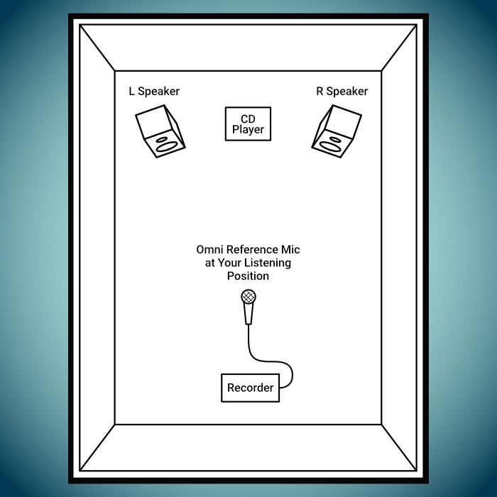
| In the listening room set up we have a pair of speakers whose centers are between 6 and 8’ apart. The listening position is between 8 and 10’ back from the plane of the speakers. This is called the listening footprint. The speakers are elevated so the “acoustic center” of the speaker is the same height off the floor as the listener’s head height.
The speakers are towed-in to align onto a point that is located one foot behind the listener’s head. Because of their directivity, the speakers send a widespread signal into all parts of the room. Only one narrow beam of this, about 1/1000 % of the whole beam, the “direct signal”, impacts the listener’s ears. The rest illuminates the listening room. |
 |
| The right speaker primarily illuminates the right ear while the left speaker illuminates the left ear. The differences between these two signals determine the imaging creates the sound stage and the images within it. The sound stage sweeps between the speakers and down both sides almost as far as the listening position. If both speakers play exactly the same track, a mono stereo signal, the sound stage becomes a single spot, front and center. |   |
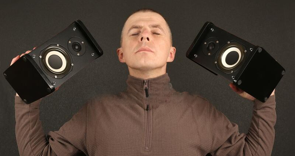
| Here is what the speakers look like from the listening position and the large center dot indicates the height and center position of the sound stage. It is at ear level, as is the acoustic center of the speakers.
If the speakers are located too far apart the sound stage widens and seems to gather itself around each speaker, leaving a ”hole” or less bright center stage image. Facing this setup the listener might want to scoot their chair forward to get closer to the center sound stage but that would only create an even deader center mage. As the listening position moves back the sound stage begins to take on the desired form. |
 |
| If the speakers are set up too close together the sound stage seems to collapse in the middle, more like a large center stage image. The listener might want to scoot their chair back to get further back to see a wider sound stage, but that would only make the center stage image even more centralized. Moving the listening position closer to the speakers will widen the sound stage. It’s not so much about close or far, seeing the sound stage is about the angles between the listener’s head and the speakers. |  |
| When the angles are correct the sound stage of a typical small musical group will be well distributed across the stage, similar to what you would see at a concert of the group.
Recording engineers mix their tracks to create the sound stage. There are certain arrangements of microphones that give a great stereo image, typical for this is a Blumlein pair, two ribbon mics held in line with each other except one is rotated a quarter turn relative to the other. This mic has a figure 8 polar pattern. A center stage image is created when the same signal is delivered to both speakers. This is essentially when a mono signal is split and sent to both speakers. |
 |
| Left of center is created by sending the same signal to both speakers except the left speaker is set a little louder than the right speaker. The louder the left speaker is the farther the center image is moved to the left. Naturally, if the right speaker is louder then the image moves to the right. This is called loudness panning of the image.
Delay panning is another way to move the image. Keep the volumes the same but add a short delay, ½ ms, to right speaker. This means the left speaker is heard first and whichever signal arrives first is where the sound is coming from, according to our ears. |
 |
| Here’s an interesting image position trick. Split the incoming signal. Use one part to create a center image. Take the other line, add a 6 ms time delay to it and adjust the level down by 2 or 3 dB. Add that back into the main signal path. The center image will move back. |  |
| Let’s use all of these image positioning devices to move a center image stage left and a few steps back. We have a center image to start with so let’s move it straight back by mixing with it a 6ms time delay that is 3 dB down. Now center image moved back a few steps.
Next we want to move things to the right a bit. We increase the loudness of the right speaker or reduce the loudness of the left speaker or a little of both to scoot the image off center and to the right. Or we could have added a short 1/2ms delay to the left speaker so the right speaker gets heard first and that means the images is coming from a direction to the right of center. |
 |
Wall Reflections
| But what happens to this hifi footprint is that it gets set up inside a listening room. Surrounded by a floor, ceiling, two sidewalls, a front wall located behind the speakers and a rear wall behind the listener. These rooms are about 16’ wide and 21’ long, sometimes larger or smaller but the width to length ratio of about 3 : 4 is retained.
Speakers are about 4’ off the side wall and 5’ off the front wall. The side and front wall speaker setbacks are never equal, always offset. The distance between listener and rear wall is 6 to 7’. |
 |
Clearly, some of the early off-axis sound paths will bounce off some spots on the walls, floor and ceiling in the direction of the listener. These are early reflections and they mess with the delicate loudness and delay signal adjustments used to create and separate images on the sound stage. Room reflections tend to ruin the sound stage.
| The first of the off-axis signals that reflect off various surfaces of the room directly back towards the listener are “early-reflections”. These early reflected signals mix with and blend into the direct signal to create a composite new signal which still sounds like the music in the direct signal, except they change the sound stage. |  |
The early reflections are not heard as separate reflections, like echoes are. Echos arrive 40 ms or more following the direct signal. Early reflections are those off-axis signal paths that arrive within 25 to 30 ms following the arrival of the direct signal.
| One of the earliest reflections bounce off the ceiling and floor. They follow the arrival of the direct signal by about 4ms. Usually, hifi setups include sound absorbing (Persian) carpet and the floor bounce is so weak it isn’t perceived but the ceiling bounce is and it mixes with the direct to change the vertical part of the sound stage. |  |
| The ceiling bounce raises the sound stage but otherwise does not change its overall wrap around shape. Most hifi listeners don’t mind the raising of the sound stage, it seems natural, more authentic than “seeing the image of a sound stage that lies at ear level straight ahead. |  |
| The hifi footprint is located between two side walls. The speakers continue to deliver the two direct signals, one LL from the left speaker into the left ear and the other right speaker into the right ear RR. Left alone we’d have the same sound stage that we’d get if there was only the hifi footprint. |  |
| Instead, we have the hifi footprint set up between a set of parallel walls. In addition to the two direct signals, LL and RR, we have the two “first reflection point” reflections, LLL and RRR. Left speaker off Left wall into Left ear and visa versa on the right. It is the all too familiar early side wall reflection. |  |
| The left speaker bouncing off the left wall into the left ear causes the apparent position of the left speaker to move towards the left wall, and the right towards the right wall. This is the same as if we placed the speakers too far apart and didn’t have any walls. The resulting sound stage is dimmed or weakens in the middle and become more present in the space between each speaker and the nearby wall. |  |
There is also a Front Wall reflection. Large boxy cabinets do not play the front wall but the more modern omni style cabinets that are rounded and narrow near the top and do play or illuminate the front walls about as well as the side walls.
Just as side wall reflections move each speaker image towards each side wall, front wall reflections move each speaker image closer towards the front wall, which moves the whole image towards the front wall. This is similar to how the ceiling bounce of each speaker raises the whole soundstage up.
| The last wall is the rear wall. If the rear wall reflection would act like the other wall reflections, it should drag the image towards the rear wall, moving it closer to the listener, opposite to the front wall bounce. However, unlike the other bounces, the rear wall bounce travels a lot further once the direct passes the listener, instead of a few feet as before, it travels 12 to 14’ further. That means the reflection is weaker and much more time delayed. In addition, we human listeners have fixed ear pinna which is great for collecting sound from what is in front or to the side of us but not good at collecting information from behind us. Rear wall reflections do not impact imaging unless they are within a few feet to the ear. |  |
| The most significant wall reflection has not been mentioned. It is the least thought of wall reflection and does the most damage to imaging. It is the cross-talk wall reflection. Here we show the right speaker with its two side wall reflections. The near wall reflection, RRR is the one that widens the sound stage. But look at the cross-talk reflection, RLL, it delivers right speaker information into the left ear. |  |
| This wrong ear misinformation almost eliminates stereo imaging. We always get our two Ds, the two direct signals, left speaker in the left ear and right in the right ear.
This is aided by the near wall bounce, left speaker off left wall into left Ear LLL and RRR. But the cross talk reflection, although having traveled further distance, being weaker and later it still delivers plainly audible wrong information into the wrong ear. The net result is in effect, no stereo imaging. Here’s a true TubeTrap story about this situation. |
 |
Bass Damping vs Image Developing
When TubeTraps were a new product, we had many dealers and reps all around the world. Our sales support effort was to help dealers demo the TubeTraps, that is to say Demo the Difference.
The demo method we promoted, because of my perspective at that time, was to sit the new customer in the listening chair in a demo room with TubeTraps stacks laid down onto the floor diagonally into the room. Play their favorite demo music, preferably something with strong, fast dynamics. Then tip the TubeTraps upright in the front two corners and the dynamic part of the music would become visceral, punchy and deeper. Dynamic bass performance would clear up.
One day we got a call from Gary Douglas, our dealer in Tokyo, who was the top TubeTrap salesman in the world. He hemmed and hawed and then began. He apologized first for what he was about to say and then proceeded to tell his story. He reported that after many tries he gave up on our “Demo the Difference” promotion program. It worked of course to tighten up the bass response in the listening room. But he just couldn’t get the customer’s attention, who had just walked in off the noisy streets in downtown Tokyo.
| His ”Demo the Difference 2.0” was to invite the customer to the listening chair in a typically furnished room and played the music. Then he’d carry a trap column into the room and set it up on a spot about half-way between the speakers and the listener position, near the side walls. He’d rotate the reflector towards the side wall, away from the speaker. Same for the other side wall and notice…. no TubeTrap in the front corner.
This location was in front of where the crosstalk reflections bounced off the side walls. In this position the far or crosstalk wall reflection was absorbed and an acoustic shadow was cast across the listening position. The customer immediately noticed the imaging magically snap into place. |
 |
That was when GD would ask if they would like to hear some more improvements and he’d haul out another pair of columns which went into the front two corners, the corners behind the speakers, where the listener would marvel again at how the bass tightened up and treble became clearer and sparkling.
And so, our demo recommendation changed from demo the dynamic upgrade first to demo the imaging upgrade first and then, once the customer was adjusted to hearing TubeTrap upgrades, to set up the dynamic upgrade.
However, we noticed it was difficult to change the Demo the Difference sequence for many of our dealers. We had developed the TubeTrap to clean up the bass by putting traps in the front two corners. We discovered later how we could use it to clean up the imaging. The dealers had gotten used to demoing the front two corners first, to clean up the bass, and demoing the side wall positions to clean up the imaging second and weren’t interested in reversing the sequence.
We learned another lesson about TubeTraps, it’s the listener who are in charge of what the TubeTrap does for them, not what the engineer intended it to do for them.
| The sketch here, as above, is for a properly proportioned listening room, such as GD had in his Tokyo Demo room or most any audiophile often has. Here we can see how separated the two wall reflecting paths actually are from each other. The image wrecking cross-talk reflection is located on the wall fairly close to the listener.
Notice that the TubeTrap stack, two traps screwed together into a 6’ tall cylinder, the circle is not against the wall but forward and out from the earlier position. Now both the stage widening and the crosstalk reflections are eliminated by this placing of just one stack. The dead side faces forward and reflectors are oriented to the back of the room. |
 |
| Here is shown the absorbing and back scattering effect of the TubeTrap placed at the intersection of the two beam paths. Stack is located to the right and ahead of the listener. Crosstalk signal from the left is absorbed, stage widening reflection from the right is backscattered into a low level delayed, backfill diffuse reflection that doesn’t shift imaging. |  |
Find Beam Intersection
| Set up a flashlight on each speaker so they reflect off the same wall, the right and later the left wall, and converge at the listening position. Use mirror on wall to reflect beams. Where the beams intersect is the image control position. Laying flashlights on the floor provides a “ray tracing” effect as the beams skim the top of the carpet. |  |
Secondary Wall Reflections
| So far we have considered mainly “primary reflections” which are those that reflect one time before they get to the listening ear. We noted one incidence of a secondary reflection in the crosstalk example above. Here we consider additional significant secondary reflections. |  |
| The near wall speaker-wall-listener beam path is horizontal, at the ear level as shown here. Above this primary beam path is the wall-ceiling secondary beam path. Below the primary beam path is the wall-floor secondary beam path. |  |
| There are 3 side wall beam paths not just one. Add one sound panel for the early side wall reflection, we hear improvement. But we still have two more sound panels to install, one above and one below the ear level panel. Otherwise, the two reflections cause vertical stage blur and widening. We’ve checked out the near wall primary and secondary reflections. |  |
| Next, we take a look at the primary and secondary crosstalk beam paths, the image killing reflections. The primary path is a ear level and as before we have the ceiling and floor secondary bounce paths. Above the primary ear level path is the ceiling-wall bounce and one below it is the wall-floor bounce. |  |
| To quiet down the image killing crosstalk sound beams we have to add all 3 sound panels. They will be one above the other, one at ear level, one near the ceiling and the near the floor. With wall to wall carpet there is no floor bounce. But audiophiles prefer a central Persian carpet between the speakers and listening chair but away from the walls to keep the room’s brighter ambience. A lower sound panel is needed. |  |
Multiple Wall Reflections
| When a speaker is located close to a sidewall we have the expected side wall reflection which slightly widens the sound stage. In effect we have 2 speakers next to each other, the real speaker and the image speaker caused by the wall reflection, and it is located just inside the side wall. In addition we hear lower level multiple time delayed reflections that occur between the wall and the side of the speaker. |  |
Some multiple vertical array speakers will have tall, narrow and deep speaker boxes. Sound waves that wrap around the vertical corners experience multiple reflections between the side wall of the room and the large side wall of the speaker. Each of the wall/speaker/wall reflections is heard as part of the early reflections, but they occur, almost like loudspeaker corner reflections, which blurs the otherwise detailed image produced by the speaker. Adding a sound panel can quiet this chatter down nicely.
Stage Depth
| Stage depth is created by adding treble range early reflections off the front wall. Speaker boxes with rounder corners, no speaker grill frame and that get narrow towards the top are particularly suited for illuminating the front wall with full range treble. |  |
| Note that bass waves also reflect off the front wall and this can cause a “phase add and cancel” effect that colors, that EQ’s the front wall reflection. This is why TubeTraps are used in this position. It positions a bass trap where the bass wave hits the front wall which greatly reduces the phase add/cancel effect while providing a curved treble range reflector to help scatter the front wall reflection. |  |
| The wall spaces between the TubeTraps now become strip reflectors which produce a natural diffractive diffusion effect so as to soften the reflection strength. The direct signal fuses with the early reflections off the front wall to create a stage depth effect that can literally locate the apparent sound stage on the other side of the front wall. |  |
| Notice the different delay paths compared to the single bounce off a flat front wall. Speaker illumiates all the poly reflectors inside of TubeTraps, lots of different time delays. The diffractive diffusion reflections occur behind the speaker. There are many time delayed reflections off the front wall. |  |
Dead Front Wall
| HiFi show rooms often have a curtain on the front wall which can be drawn over the stage depth traps, eliminate the front wall reflection and place the image between the speakers, |  |
Acoustic Zoom Lens
Early in the days of hifi, and surely still today audio nuts gather together to listen to each other’s sound systems. It was during one of these gatherings where the front wall was setup to bring out the stage depth effect.
| 16” TubeTraps were located in each of the front corners and in the middle on the front wall. Smaller traps were spaced between these 3 big traps to develop the diffractive diffusion effect of wall strip reflections and minimize low end coloration reflections.
The center trap was always referred to as the image trap. It seemed to illuminate the central stage position which is usually where the lead singer or instrument is located on stage. Reverse the trap position, rotate the reflector to the wall and the center stage images darken down a bit so they are illuminated equally as elsewhere. Someone suggested that if instead of rotating the reflector toward the wall we could slide the center image trap a little forward, it might brighten up the center stage a bit. Instead of brightening center stage image, the center stage image took a step forward, moving closer to the listener. |

|

| Naturally, the center trap was slid a little further forward and the image accordingly moved forward some more. This zoom lens effect continued as the center trap was moved up through the plane of the speakers. The center image was floating somewhere between the listener and the plane of the speakers.
This was an astonishing effect we were witnessing. As the center trap was moved forward, ahead of the plane of the speaker, the center image kept moving forward but at the same time faded and died out. The center reflector was no longer reflecting the wave from the speaker towards the listener. |
 |
| Later we made a custom image zoom trap with 2 reflectors, one on each side, so the reflectors always faced the speakers and tried the zoom lens again. It worked perfectly behind and in front of the plane of the speakers. And we retried the experiment. |  |
It worked as before and it seemed that when the zoom image trap was about half-way between the plane of the speakers and the listener, the acoustic image seemed to be right in front of the listener. We were zooming Acid Queen by Tina Turner.
| About halfway between the plane of the speakers and the listening position the image had grown so big and moved so close it was literally in our lap, she was screaming singing right into our face. It was as if we had become the microphone that she was screaming singing into. | |
Pure sonic imaging, no drugs, alcohol or mind altering anything just sound. It was so intense it became an unbearable experience for any length of time. We’d jump out of the listening chain, taking turns standing the intensity of it as long as possible, usually not more than 10 seconds. We just had to slide that double sided image zoom trap back to the front wall to calm things back down and get back to listening to music.
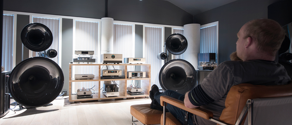
Silent Speakers Great Soundstage
| In a poorly set-up room there is easy to know that the speakers are playing, you can hear them, you can point to where the sound is coming from and it will be coming from the speakers. In a well set-up room it’s hard to actually know that the speakers are even playing, they seem to be silent. |  |
And when you point to where the music is coming from, it’s not the speakers, it’s up and ahead of you, between the speakers, behind the speakers and out to the sides of the speakers. The music seems to come from a large sound stage floating in space in the front part of the room. The better the room setup is, the more the soundstage wraps around the listening area.
The ultimate listening room was coined around 1990 by Bruce Brisson of MIT Cables: 2C3D, 2-channel 3-dimensional soundstage. It was developed by a collaborative effort between 4 manufacturers: ASC TubeTraps, MIT Cables, Spectral Audio and Avalon Acoustics. Once the system was developed, other high-end components were combined to produce a similar holographic audio performance.
In the traditional hifi setup the soundstage appears as a crescent shape space in which various instruments or combinations of instruments, including vocal of course, seem to be floating in space and projecting sound from their location. We can’t really see the visual image of each instrument but we can see where they are located on the sound stage, and we can point out right where they are located.
What is interesting to observe is that in the well set-up room you can get up and walk left and right, and the sound stage moves left or right with you. In a poorly set-up room you might enjoy a reasonable sound stage but when you get up and move to the left the stage collapses onto the left speaker or right speaker if you move to the right.
Non-Room Early Reflections
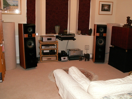
| HiFi gear back in the 70’s used to be piled up in the front of the room between the speakers, the “golden calf” era in audio. It made a great visual presentation and included turntables, reel to reel players, preamps, equalizers, amps and the stands to support them. Suddenly in the mid 80’s that gear setup literally disappeared. |  |
| Audiophiles had discovered that early reflections off all that equipment stacked between the speakers was causing the stereo image to be limited to a ball of fuzz between the speakers. |  |
Where’d all that gear go? It was moved down the two side walls and the interconnect cables became longer and longer. There was nothing but clean air surrounding and between the speakers.
| Today the gear setup has changed again. The amps are back near the speakers and preamps not far away but instead of being up on stands they are down low, near the floor, often set back behind the plane of the speakers. Turntables were moves far away from the speakers to distance the record platter from the wave impact from the speaker. |  |
This compromise position minimized the strength of the treble range reflections off the equipment. It was far enough away and behind the speakers so the wave strength that hit it was weak and the reflections were cast away from the listener.
Also, some equipment was removed from the audio chain. No equalizers were to be found. The only signal processed was the original unadulterated signal. We used a “linear audio chain” and no accessories.
Effects of Reflections
We have a direct signal that is recorded along with numerous early and late reflections. These reflections in the recording have an effect on the listeners impression of the timbre of the sound and the location of the image of the sound.
 In hifi playback the goal is generally for the listener to have a listening environment which allows the original timbre and image to be perceived. Otherwise, the early and late reflections in the room additionally change the timbre and image of the recorded signal.
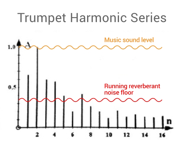
Here below is a graph, based on tests, which outlines the effects caused by early and late reflections. The graph below shows the types of effects based on the time delay and loudness of the reflection. A multiplicity of reflections creates a multiplicity of effects. Very early reflections, within 5 ms causes changes in the position of the image.
Early reflections between 5 and 35 ms delayed cause image shift and tone coloration. This is because very and early reflections are sound fusion reflections, they become part of the direct signal.
Late reflections between 40 ms and 70 ms create the effect of space in which the direct sound was created. Very late reflections, beyond 70 ms, create a confusion of noise being added to the music which compromises the clarity in the hearing of the music which degrades the appreciation for the quality of the music. These reflections will come up again and again as we review the imaging of musical playback.
Image Stability
| In a sonically quiet room there can be found a number of objects, each of which causes a different sounding early reflection. The tonal differences are due to the variation in shape, size, composition and location. Shape and size determine the low frequency cutoff of the reflections. Composition tends to reduce the higher frequency reflectivity and location varies the sound of a reflection because the tweeter and midrange speakers do not have a uniform beam pattern, different frequencies will be louder or quieter at any given location in the room. |  |
| With the speakers set up to produce a fairly strong mono stereo center image, instead of playing music use a signal generator to run the system through a “sine sweep”. Ignore the variations in loudness, particularly in the bass range but concentrate on the location of the mono stereo center image as the sweep moves into the upper treble range, above 500 Hz (octave above middle C). The tight center image will not stay in one place, it will move left and right, up and down along a path as if it was flying around between the speakers. |  |
| Clearly, early reflections cause problems with the imaging of the stereo system. By adding larger sized sound panels close to the speakers, the spread of the off-axis sound, the beam pattern of the speaker, is narrowed which reduces the number of off-axis early reflections. The stereo imaging clears up and its position is stabilized. |  |
Imaging Omni Speakers
Omni speakers play sound equally in all directions. About 10 % of the hifi speakers are omni speakers. The original popular omni speaker was Bose 901, in the 60’s and continues to evolve omni speakers. Walsh Ohm speaker came in the 70’s and continues through today with their call to action “hear the music not the speakers”. Omni speakers have evolved, MBL, Linkwitz, Duevel to name a few.
With Omni speakers the same sound expands equally in all directions. One of the more curious aspects of omni speaker owners is their insistence on having no acoustic treatment. The more reflections the better which leads us to explore what the imaging of omni speakers in hard surfaced rooms is like. We are not talking about omni speakers being used in large venues, where they seem to deliver fantastic sound, but when used in regular sized home listening rooms.
Omnis, like most all other speakers, deliver a direct signal before any of the reflections arrive. This creates a first arrival effect which in this case retains a semblance of a left and right speaker playing stereo.
Outside of this, the imaging as we “know it” seems to disappear. When an audiophile, who regularly listens to a precision imaging system, visits an omni room what the “sees” is a giant “fog bank” of sound devoid of any detail. It’s not like sound beams blasting through a foggy sound stage, there are no image beams cutting through the fog bank of sound, no sound stage, just great music.
With omnis, there is formally speaking, no image to be seen. But dedicated omni-philes talk about the sound stage of their system even though no L-R ear information is being received. Their image is not a perceived image, it is their imagined image. Concerts, night clubs, choirs all have traditional footprint. It’s just that in audio we are wary about “hearing” what we wanted, believed or hoped to hear rather than the truth of what we did hear. With omni’s, it’s all good, we get to relax and hear want we want to hear and don’t give it a second thought. Stressless playback.
Listening Chairs
The traditional listening chair or couch has a cloth surface and a low back. The listener’s head is up and well above the back rest of the chair. The chair is fabric and has no sound reflecting properties. Armrests tend to be universal.
| However, we often Queen Anne style Wing Back chairs in listening rooms. They are fabric and sound absorbing. Their high back and wrapped sides act as a sound barrier, blocking reflections from the back of the room and the sides. Quieting down the back wall reflections removes distracts from behind and tends to make for a more focused and predominant sound stage up front. |   |
There is a clear preference with audiophiles which is to quieten down the sections of the side walls that are directly to the side of the ears. This isn’t about image reflection control it’s about reducing the directional distractions, like the rear wall but here, the walls directly to the side of the listening head. Often this is accomplished by positioning a few sound panels on either side of the listener. The Wings of the Wingback get the same job done without further damping down the room and allowing more visible wall space.
| The leather versions are not the desired model because the leather creates many very early reflections that interfere with directional and clarity cues that are otherwise readily abundant in a traditional hifi set up. Leather wings also reflect strong early reflections directly into the opposite ears, similar but more intense as crosstalk reflections. |  |
Ambience
Ambience is a time delayed diffuse condition in the upper treble range of sound. A diffuse condition exists when the reflected sound seems to have no particular sense of direction. When sound is initially being reflected it has a sense of direction, most of the present discussion about sound has been about sound that has a sense of direction.
| If we wait a little longer we’ll see that the reflecting sound in the room is becoming more and more random in nature, it is becoming ambience. Diffusers in the room scatter sound and accordingly they reduce the time it takes for early reflections to be converted into ambient random reflections. Sound reflecting around a room dies out because of the absorption in the room. When diffusers are added to the room the reflections become ambient sooner than otherwise. The earlier ambience is created, the louder it is and easier to hear.
There are two kinds of sound scattering devices, one is referred to a Diffusor which is trademarked by RPG and the other is referred to as a diffuser, anything that scatters treble range sound. The classic diffuser is a “poly”, a column that has a curved surface, not a cylindrical column but a column made out of an arc, a segment of a large cylinder. The poly diffuser is commonly used in recording studios, concert halls, auditoriums and professional listening rooms. Stand in front of a wall, about 3’ away and perform a sound check “Check, check, testing, 1, 2, 3, 4” and as you talk at the wall you can sense you are speaking towards a wall. Stand in front of a poly diffuser, about 3’ away and talk at it, You can’t sense that your are talking towards a large flat surface. It seems like you are talking towards a sound absorbing panel because the diffuser reflection is so quiet, because it is so spread out. |
 |
The poly has a smooth, flat, curved surface. It acts like a curved mirror does with light waves. Because it is a flat curve it doesn’t have irregularities all along it’s vertical surface. The ear is very sensitive to the changes in elevation of high frequency sound, which is why a fly buzzing around is so irritating. If we had irregularities along the flat curved surface, like we see on climbing walls we would become very distracted by the multiplicity of vertical reflection points. The poly is a diffusing surface that does its work without calling attention to itself, sonically speaking.
The poly diffuser is applied to walls and ceilings. When a poly is located at an early reflection location, the reflections appear to be absorbed because they are much quieter than a flat wall reflection. But they aren’t absorbed, they are scattered about the room. When we want to control an early reflection we can add a poly diffuser instead of a sound absorber and use that reflection to feed the buildup of diffusive ambience in the room.
PolyDiffusers work well with TubeTraps. When polydiffusers are stacked side by side where the meet is a shallow V intersection. That’s where the TubeTrap is located. The horn effect of the reflecting part of the open shallow “V” intersection between adjacent polys is erased by adding TubeTraps in front of the “V” intersection line. This creates a broad band diffusion/absorption wall, treble diffusion and bass absorption.
Vertical diffusers in listening rooms create strong lateral diffusion but do not contribute to vertical diffusion. Lateral diffusion is very interesting and easily heard by our ears which are also laterally deployed. Usually carpets in room absorb the vertical component of reflected sound leaving only the lateral component of diffusion as the remaining ongoing compliment of ambient sound.
Spaciousness
Spaciousness is a unique condition of reflected sound. It occurs when there are very time delayed reflections of the direct signal entering the ears from either side of the room. Spaciousness in a listening room is a highly valued sonic accent because it removes the feeling of listening in a small room. The room feels opened up and yet at the same time not open as if there were no walls at all.
| It’s that the feeling of a large flat wall nearby is eliminated, replaced with in indistinct presence of something out there. It’s the kind of reflections we get when we are in a forest, where we are surrounded by tall round sound reflectors. The space around us doesn’t sound like open space and it also doesn’t sound like a hard wall bounded space. This space sounds like it is open but partially, intermittently occupied. |  |
| Spaciousness has an acoustic formula. It is created by time delayed, low level lateral reflections from multiple reflecting sources at different lateral angles to the listener. Early lateral reflections are delayed between 25 and 60ms while late lateral reflections occupy the range of 60ms and beyond. Early later reflections allow the sound stage to wrap around the listener while later lateral reflections create the spaciousness effect. Earlier reflections are 10 dB and later reflections are 20 dB below the direct signal. |  |
| If a speaker is 10 from the listener and a side reflection flat wall surface is 17’ from the listener, the flat wall reflection is only 20 Log 10/34 = -10 dB lower than the direct signal which is too loud. Flat wall segments cannot be used to simulate spaciousness in the small dimensions of listening rooms. |  |
A cylinder shaped reflection spreads sound out laterally. The lateral reflection of sound off a cylinder of radius r is Ld = Lr – 10Log d/r, where d is the distance from the center of the cylinder to the listener. The lateral expansion of sound off a cylinder is -3 dB per doubling of distance. That’s why line source speaker arrays are popular for projecting sound into the distance, compared to point source speakers where the sound level drop off is -6 dB per doubling of distance.
| A cylinder shaped surface, instead of a flat wall, is located 17’ to the side of a speaker and 17’ to the side of the listener. The speaker as before is 10’ from the listener. The sound level at the face of the cylinder is 20 Log 10/17 = -4.6 dB below the direct signal. This is reflected by a 1’ radius cylinder. The sound drop off from the cylinder to the listener is Lr – 10 Log1/17 = -15 dB.
The overall drop off of sound between the speaker, to the cylinder then to the listener is Lr = -4.6 dB -15 dB = -20 dB below the direct signal. A flat wall reflection over the same path is -10 dB down and too loud. |
 |
But the room width to develop the timing for lateral reflections is 42’ which is too wide for typical listening rooms, which are about 16’ wide.
Spacious Sounding Listening Room
| A method was developed for using certain flat reflecting surfaces of listening room to illuminate side wall cylinder reflectors. A segment of the sound from the speaker is allowed to reflect off a segment of rear wall that is about 3’ wide and located about 2’ in from the rear corner. The width of the speaker setup is typically 4 to 6’ off the side wall. A segment of sound beam from the speaker travels down the length of the room, hits the dedicated wall position and reflets back up the room but in an outward angle.
This outward angled sound beam impacts a set of sound reflecting cylinders lined up along the side wall to create a pattern of time delayed later reflections and the associated wrap of the sound stage plus that spacious sense of a listening space. |
 |
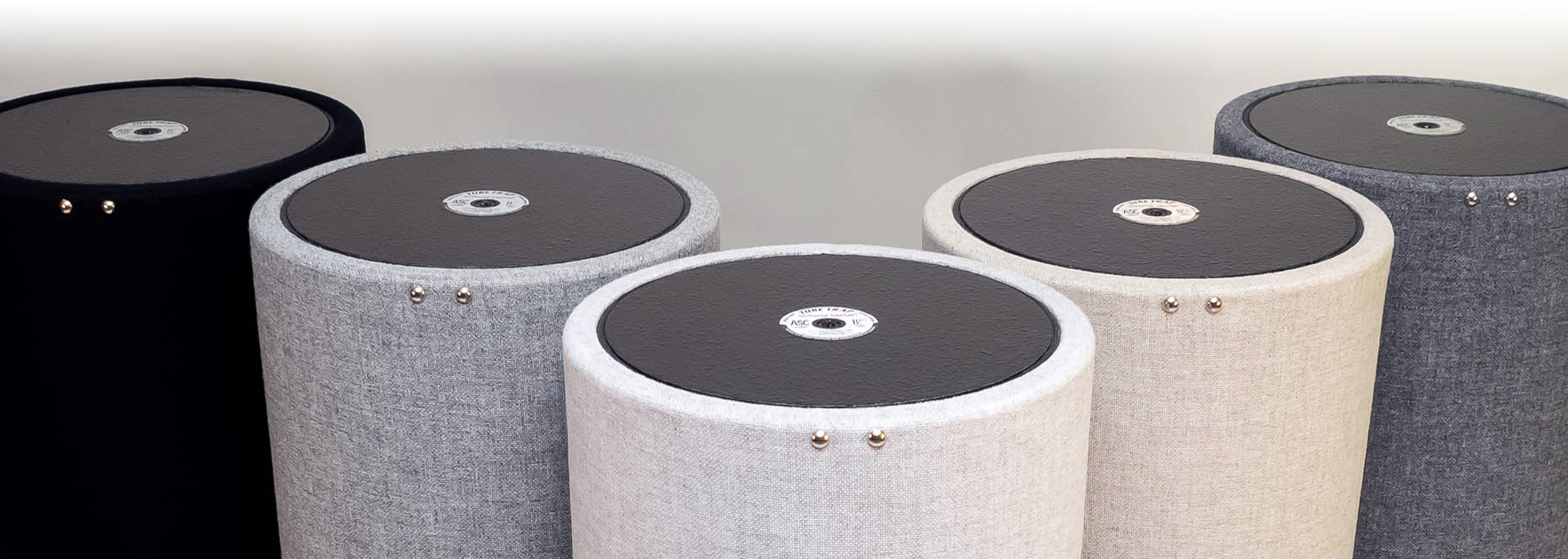
| With TubeTraps, only the front half of the cylinder is treble diffusive, and the other half is treble absorbing. Imaging and spaciousness are treble range sound effects.
The TubeTraps are set up along the side wall. The front half is set facing the rear wall and the back side, the dead side is facing the speakers. The wall reflections to the side of the listener are absorbed. |
 |
| The time delayed rear wall reflections are scattered off the front sides of the TubeTraps along the side wall. This creates a set of time delayed low level lateral reflections.
And notice that the right speaker is illuminating the right ear with delayed scattered reflection from the right side while the left speaker, playing a different sounds, are illuminating the left ear with delayed scattered reflections off the left wall. The listener’s two ears are getting different time delayed lateral signals which meets another criteria for spaciousness, which is that the left and right ears hear different spaciousness signals. |
 |
Ambience Plus Spaciousness
Ambience frames in the images on the sound stage, not literally as in a picture frame but sound framing within the sense of time. The quiet chaos of ambience is the overall fluctuating glow of the room as it is filled and drained with the slowly changing color of tonality, dynamics and tempo of the direct signal. The comings and goings of sound, as newer sound is filling the room while the older fades away.
The spaciousness aspect is the presence of a field of sparkles to each side of the listener that reflects a distant glimmer of the music in the direct signal, as if the color of the image action on the sound stage it picked up and reflected, flickered back into the audience by the distant columns to the side of the listening area
———————============= The End… for now =============———————