Art’s Presented Papers
 Art Noxon is a fully accredited Professional Acoustical Engineer with Master’s degree in both Mechanical Engineering (Acoustics) and Physics. He invented the TubeTrap in 1983. He created Acoustic Sciences Corp in 1984 to manufacture and distribute the TubeTrap. A prolific inventor, he has 12 TubeTrap related patents and has developed over 150 other acoustic devices and counting. A scientist, lecturer, writer, and teacher of acoustics, Art Noxon has presented numerous AES papers, magazine articles, white papers, lectures and classes in the field of applied acoustics.
How TubeTraps Opened a New Realm in Audio Playback
It’s been asked: How have TubeTraps Open a New Realm of Precision in the Performance of Audio Playback Systems? Well, audio minded people know to place TubeTraps in the corners behind the speakers and they know what benefits are delivered. But what isn’t so easy to answer is why it works the way it does. Standard audio tests did not produce results that correlated with customer satisfaction. However, when a modulation transfer function MTF test is applied to the woofer of the audio system, the results do correlate with customer satisfaction which directly leads to the concept of musical intelligibility being a highly valued audio system performance indicator. Investigations into the physical acoustics that produce the MTF results account for why TubeTraps in the front corners of the listening room are so well received in the audio community.
This concept is then extended a full octave lower, into the subwoofer domain which is dominated by sympathetic vibrating walls and ceilings. To correct for the blurring of musical intelligibility due to uncontrolled structural vibration a new style of listening room construction was developed using constrained layer damping CLD techniques. This extends the highly valued musical intelligibility performance down through the subwoofer range.
A Short History
What would come to be the iconic bass trap was invented about 25 years ago in 1983 by me, a young acoustic engineer/physicist/speaker builder named Art Noxon. It turns out that I had also unknowingly invented in my basement an improved version of the “functional bass trap” which was something developed in the RCA labs in the 1940’s and revealed to the public in 1950 by the chief engineer Harry Olsen in his classic technical book, Acoustical Engineering.
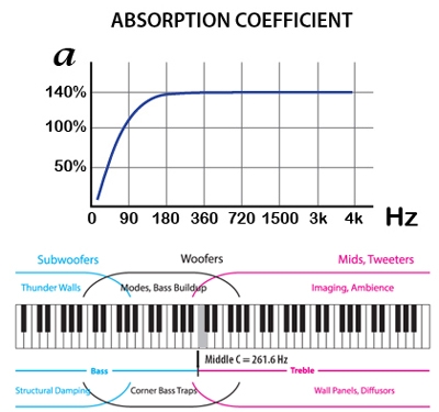
| Found in this book are untold numbers of RCA audio/acoustic lab secrets. Still, it took another 30 years and a patent search before I discovered the functional bass trap and the great book where it was disclosed. Frankly, I was relieved to discover my work fell right in line with and was a natural extension of earlier work in this same area. Even the same peak efficiency of 140% reported by Harry Olsen for his functional bass trap is a standard measurement of the TubeTrap product line.
The first hand made commercial TubeTrap was discovered by Rob Sample, a HiFi rep who passed through town every month or two. The TubeTrap had been gathering dust in two corners of a dealer demo room, behind a set of Magnipans, helping to reduce the strength of the back wave that would otherwise bounce out of the corner and right back towards where it came from, the huge Maggi diaphragm, where it pushed the diaphragm around, distorting the sound. |
 |
| This TubeTrap was even covered in Maggi white fabric, purchased from the Maggi factory. The store staff pulled the trap out and put it back in while Rob listened. |  |
The next day I got a call from Jon Dahlquist in New York, accent and all. I didn’t know who he was yet but he certainly asked wonderfully technical questions, it was such a relief to talk to another engineer about this device. Jon built the Dahlquist loud speaker and Rob Sample, his NW rep, had called him about what he had witnessed. After a little visiting Jon ordered a set of TubeTraps, I built and sent them. Never thought about money, I was happy that someone wanted to check them out.
| I made the acoustic crossover to his spec and slipped it into the front of each trap as soon as they arrived and shipped them back the next day. He loved it and invited me to help him set up his demo room at the summer CES in Chicago where he was unveiling for the first time a time-aligned loudspeaker, the DQ-20. I didn’t know what CES was but I agreed to go. And within hours of setting up the demo room there, I was signed by Noel Lee and became the next new product exclusively distributed by Monster Cable. |  |
 |
| A week later he called back and loved what they did for the bass but wanted less treble absorption. I couldn’t believe anyone could hear that well. Still, I asked what the crossover frequency should be and he paused, as if he was a chef, imaging how much seasoning to put in, and then told me. |  |
Noel was an electrical engineer/marketeer who had realized that the electronic interconnects in the audio chain needed to be cleaned up. He had recently signed Bruce Brisson (now MIT) to clean up cable interconnects and now he signed me to help him clean up the acoustic interconnect. Despite the Monster marketing machine, big ads, dealer training and stocking inventories, the pipeline was filled, primed and ready to go but no one came, nothing happened. Monster never released their second PO and eventually TubeTraps (CSP-1s back then) were dropped from the Monster Line Card.
Now, with no hope of outside sales, a completely rebuilt factory full of production materials, I became a traveling TubeTrap salesman, knocking on recording studios doors, not much different from a vacuum cleaner salesman. But they loved them and I paid my bills, including the expensive international 1-800-ASC-TUBE phone bill. I’m glad I did because one day, with absolute no warning, the phone starting ringing off the hook, TubeTrap orders came in from HiFi shops all over the world.
| What happened was that J P Moncrieff had finally published his long awaited review of TubeTraps in his IAR, International Audio Review newsletter. Noel Lee had given him a few traps to review. JP followed directions, put a set in the corners behind the speakers and all was good. And then JP asked for a few more, and later a few more and on and on this went for nearly a year before the review came out. JP had even interviewed me but it had been so long, I forgot all about it. What started out to be a review of one pair of TubeTraps in each of the front two corners of the room ended with him reviewing his own TubeTrap invention: The walls of his large listening room were lined with double stack TubeTraps on 3 foot centers, all around the room. And then the reflection panel of each trap was tweeked within an accuracy of “¼ inch”, which no one believed was possible, at that time. Despite this, the TubeTrap became a must have HiFi upgrade, an overnight success story that took 1 ½ years to happen. I will always be indebted to Rob Sample, Jon Dahlquist, Noel Lee and JP Moncrieff for applying their personal vision, imagination and power to the coming out party for the TubeTrap and what it stands for. |  |
There was no such thing as “room treatment” back then except for treble range Sonex foam panels. But this new class of room treatment was nothing like daubing up a little treble splash in the room. This was a new listening room upgrade system, starting with a few traps in the corners, and evolving through different stages which end with floor to ceiling stacks on 3’ centers around the perimeter of the listening room. In its least form, a pair of traps in the corner, the speakers began to behave themselves. And in its ultimate manifestation the listening room was transformed into a magical palace of sound and ambience, imaging and sound stage, a fantasy listening room, a magically transformed listening room which evolved over time into the classic 2C3D reference listening room.
We Know TubeTraps Work, But Why?
Most people who have listening rooms do not also have access to as many TubeTraps at they want. They find themselves very happy with the results derived from a few stacks of traps, starting in the two front corners of the room. I kept trying to measure what they were being pleased about. The basic setup was always the same: Put a set of traps in the two front corners of the room, the corners behind the speakers, rotate the reflectors in towards the speakers and step back and let the Traps do their magic. It always worked and no one had to know more than to be able to find the corner behind the speaker, to become an acoustic guru.
Corner Bounce ControlAt first I thought the reason TubeTraps were working was the original reason the TubeTrap was used which was to kill the phase add and cancel distortion effects due to the corner bounce out from behind the speaker. The Traps certainly reduced the comb filter action in the frequency responses curve of the speaker. Measurements confirmed that the comb filter effect was minimized by putting the bass trap in the corner and I published this in my first AES paper. But comb filter correction didn’t correlate with what the HiFi buffs who bought the Traps said when they and called in with a thank you and the list of their observations. |
 |
Audiophiles who bought TubeTraps said they liked the improved bass smoothness which was expected because the phase add and cancel effect had been addressed. But then they continued, saying they also enjoyed the bass extension, punch, dynamics, and the surprising absence of a one note or drone tone bass being replaced with a musical bass line. All of these notable improvements were in the bass range although I was hard pressed to account all these improvements to correcting a comb filter reflection out of the corner behind the speaker.
| If that wasn’t perplexing enough, they went on into the treble range, describing their amazement as to how could a bass trap could improve imaging, musicality and sound stage, all of which are aspects of listening that belong to the treble range. Certainly the treble diffuser of the TubeTrap is nice for ambience and some spatial detailing but it couldn’t be that good. Most all of their observations couldn’t be accounted for by absorbing a bass bounce and adding a treble splash out of the corner. So the search for an explanation about how they did what they did was not over. | 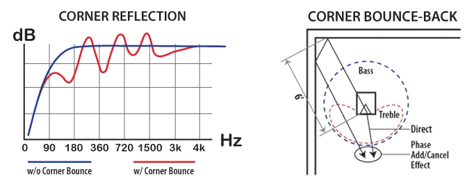 |
Reverb Decay Control
Adding bass traps in a room changes the decay rate, speeds it up. Absorption causes sound to die out faster in a room. When a sound is made in a room, we first hear the sound and then we hear the echoes and then the reverberation, which dies out over a relatively long time. If we make a continuous set of sounds the reverb of the first sound is added to the reverb of the second sound which adds to the reverb of the third sound and so on until a fairly continuous din of background noise builds up. This din of noise keeps people from hearing quiet sounds being made or quiet parts of louder sounds being made. Trying to have a conversation across an empty gym is a good example of how sound masking this din of reverb noise can be.
| The recommended RT60 is not the same for all frequency ranges. In the midrange it is about 0.75 seconds, while in the high frequency range it might be 0.9 seconds and in the low frequency range up to 1.2 seconds. By measuring the RT60 in different frequency ranges and adding the right amount of absorption to the room in these different frequency ranges, the recommended RT60 can be achieved.
Notice that EQ was not mentioned. EQ does not change the decay rate in a room, it only changes how much sound is being put into the room at various frequencies, compared to other frequencies. EQ is a volume control, not a reverb control. So we added TubeTraps to the room with sound panels and achieved the recommended specification. This plus comb filtering the corner reflection must be the magic combination that makes rooms sound great….it must be what TubeTraps are doing right… |
 |
| Well, these rooms did sound a little better but actually not as much as expected. Definitely there is more involved with room acoustics and TubeTraps besides RT60 adjustment. I had to continue to broaden my search for the answer. |  |
Room Mode Control
The next idea I had was that they trapped room modes. It was well known in room acoustic circles that all room modes always have pressure zones in the corners of the room. Adding bass traps to the corners of the room certainly should add damping to all the room modes, which should reduce the sharpness of the modes, reduce their phase add and cancel effects and produce a smoother frequency response curve.
Acoustic testing of modes did show these changes: Room mode resonance, the Q or sharpness of the room mode resonances were reduced from 30 and 40 to about 10, which sounded good enough. And yes, the frequency response curves showed changes, some smoothing in the bass range but only to a very small degree, on the order of ½ to 1 dB, certainly no more. What a disappointment. This small amount of improvement is below the threshold of perception of sound level difference in a test lab setting, 1 dB. Certainly no one could hear this tiny acoustic EQ adjustment that came from adding corner bass traps. I published these results in another AES paper.
| This couldn’t be the reason for the glowing reviews, customer acceptance and appreciation. The search for what TubeTraps were doing right when placed in the front corners of the listening room continued on. Such small changes in the frequency response of the room simply did not match the thrill and wonderment the audiophiles continued to regularly report after installing TubeTraps in their rooms and they were always the same: Tighter, punchier bass, losing the one note bass, getting deeper extension to lower bass and achieving something called musical bass. This is what one might expect from a good bass trap. However, the observations went on, and were not limited to the improvement of bass response. Imaging, musicality, stage detailing were all clearly identified over and over as being the unexpected but very significant improvement in the audio performance due to adding TubeTraps into the room. How could adding bass traps to a room make significant improvements in the treble range performance of the room? Until I could sensibly answer that question, I couldn’t know what TubeTraps were doing right in listening rooms. |  |
Testing, Testing and More TestingTo make tests in the lab and also in customer rooms that tracked the before and after “treatment” we were using the Crown Techron, a portable FFT analyzer that produced wonderful ETC Energy, Time Curve water fall displays, Reverb decay curves and frequency room response curves to just name a few. The problem we kept having was that we were losing resolution when we worked down in the bass range, which was where we wanted to work. |
 |
We could focus in on how the sound level changed over time but couldn’t pinpoint what frequency was involved. Alternatively, we could pinpoint the frequency we wanted to look at but we lost all observable detail in tracking how the sound level varied over time.
It turns out I got caught by the classic “uncertainty principle” dT x dF = 1. For example if we wanted to look at 30 Hz, we can’t just look at a single frequency we have to box it in, say, look at it within a 2 Hz bandwidth, so we actually look at data between 29 and 31 Hz in order to see what 30 Hz was doing in the room. Here’s the problem: dF = 2 Hz. This mean: dT x 2 Hz = 1 or dT = ½ second, the fluctuations in time were being averaged over one half second. Well, that was way too time averaged to do us any good. We needed to see changes on the order of 1/10 second at least or faster but then our dF was 10 Hz and the frequency we were looking at was a 10 Hz bandwidth, not a frequency.
So I decided to go to a Syn-Aud-Con meeting. Everyone who went to this high end sound system group had a Techron and were using it regularly. I went to find out what the heck I was doing wrong and how to get good data results in the low frequency range. Ultimately, the uncertainty principle won and I gave up using the FFT analyzer to figure out what was going on in the low frequency range.
Let’s backup to the beginning again. When the TubeTrap was invented I began to test it. We got the local university to loan us their concert hall reverb chamber. It wasn’t being used because they changed from acoustic to electronic reverb reinforcement. We lived in that concrete room for 5 years. I had one tech there almost constantly. We were testing the sound absorption of every model of TubeTrap at every frequency from 25 Hz through about 700 Hz. That’s about 700 data points per test run. In a 10 second reverb chamber it takes about 10 seconds to charge the room with sound and 10 seconds for it to discharge which ended up being 30 seconds to do get one test point. That amounts to 350 minutes, or 6 hours per test run. At first it was thrilling but after a solid year it was getting tedious.
So we experimented with speeding the test up. We took known traps and did the test faster, comparing the results with the known result for the product. We managed to speed the test up to 1/8 second tone burst test cycle, that’s 8 tone bursts per second and each tone burst was a different frequency. This wasn’t FFT testing it was just a tone generator, sound meter and strip chart recorder. This direct testing system did not have any df x dT = 1 problems that we knew of and we always got great pure tone absorption data. If we ran the test any faster than that, things got blurry and we lost our ability to resolve details. By then our testing had become automatic, and each 700 point data run now only took about 1 ½ minutes. We had nailed high speed bass trap testing.
| So, I’m heading to Syn-Aud-Con with my dT x dF = 1 problem in mind and finally am sitting in the class with quite a few people who would become audio industry leaders in the future. Instead of what I wanted to figure out, a European scientist, Victor Peutz of Netherlands, walks into the room. He has come over to the US to introduce us to “intelligibility” measurements and what they mean. |  |
Sound contractors have long been required to meet sound level standards, where every seat in the house had to have roughly the equivalent sound level. Then a new spec showed up for sound contractors to meet. Every seat in the house had to have the same spectral balance. After that they were saddled with another specification to be met, the house curve. This is an EQ’d sound spectrum which also had to be delivered within a couple dB to every seat in the house. Everybody in the audience was guaranteed to be exposed to the same sound level and same EQ. The next house spec, thanks to our European counterparts, was going to be the STI, Speech Transmission Index and it measured speech intelligibility. This was the class where we were going to be trained to understand this test and how to perform the measurements.
The test they used was not initially an FFT test run on the Techron. A protocol was later developed to do it. But for now this was a very different test, something called an MTF, a Modulation Transfer Function and B&K made the RASTI testing system, RApid Speech Transmission Index. MTF is sort of like Morse Code, da da daaa da da… And the question is how fast can you send the code before it loses the clarity and becomes a garbled blur of sound instead of a set of discrete tone bursts…. And guess what the RASTI tone burst rate was? Right, 8 bursts per second.
By the way, photography engineers learn a lot about MTF. In photography it is about the silver crystal size. If we have lots of light, we can have slow film, lots of small silver crystal which produce sharp differences in brightness, and the ability to see very fine lines. If we don’t have much light we use fast film which has large crystals which have the effect of producing gradual differences in brightness. MTF measures how strongly the light changes from bright to dark, depending on the closeness of line spacing. This is similar to MTF in sound, where we measure the difference in loudness of a gated sound, measuring the sound level change between when the sound is on and off and on again.
| Notice, 2 eyes, and 2 ears. Same kind of system: Stereoscopic is 3d visual imaging and stereophonic is 3d auditory imaging. Notice, the eye event reaction time is 1/30 second which lets fast slide shows become moving pictures, and notice that the ear event reaction time is the same, only here all the reflections inside of that time become one, and outside of that time become separate echoes.
Even more intriguing to me is that photography is a recording of optical spectrums which varies depending on where in space you happen to be looking. All while audio is the recording of sonic spectrums which varies depending where in time you happen to be listening. Space-time interchanging And finally notice, photography engineers and their gear manufacturers are all about controlling the level of visible detail, the photographic MTF for their customers, while audio engineers and their gear manufacturers see nothing, know nothing and say nothing about audio MTF for their customers. In fact, they never even heard of it. |
 |
Modulation Transfer Function
It turns out that when people talk they create on the average, world wide, about 8 separate sound level fluctuations per seconds. For this speech testing they used two frequencies, one was a 2 octave wide noise centered at 200 Hz and the other was 2 octaves wide centered at 2k Hz. Great Scott! We were doing the same test except that we were using gated pure tones instead of gated noise. I stayed up all night and wrote a short white paper and in the morning I asked Dr. Peutz to read it. Sure enough, he confirmed to my delight that we were actually running narrow band MTF testing, narrow band intelligibility or articulation testing in HiFi rooms. We named our version of playback intelligibility MATT. Musical Articulation Test Tones and it has become one of the audio acoustic reference test signals in the industry. See Stereophile Test CD #2, Track 19. Later I discovered that the same kind or research about sonic pulse rate for music had been done and again, musical sonic events occur worldwide average at 8 times a second, the pattern of dynamic pulses for music is on the average 8 Hz. What we had stumbled into was a, maybe the test for musical intelligibility.
| Something else was very interesting about this test. It was the only test we ever tried that produced results which were in sync with our customer’s enthusiasm for having adding TubeTraps, at no small expense and inconvenience, to their systems. Instead of showing them ½ dB adjustments in the frequency response curve, we were showing them 3 to 10 dB improvements in their musical articulation response curve. In other words, adding TubeTraps to the room allowed the room to change sound level more rapidly, to be more responsive to musical dynamics. It’s not how loud the music was during a pink noise test or frequency sweep that mattered, it was how quickly it could respond to changes in loudness. Sorta like dynamic headroom in amps, except this was the acoustic side of the situation. | 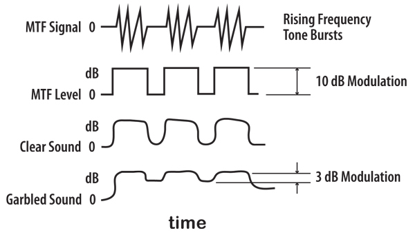 |
When we ran a MATT test in someone’s room before they were trapped, they might display dynamic acoustic headroom of say 3 to 5 dB between 30 and 700 Hz at an 8 Hz tone burst rate. After Traps were loaded into the room we would easily measure 6 to 10 dB dynamic acoustic headroom across the board. Finally we had a test that made sense. When we ran the test, the customer always wanted the low headroom bandwidths fixed first, not suckouts, modes or room boom. Garbled sound was worse than anything else. And even more, they knew where these problem areas were because they could pull albums out and play the passages that would also demonstrate where the rapid dynamics were garbled.
Wow, the audiophiles already knew all about this type of garbled sound problem. I’m the one who didn’t know about it. They knew what was wrong with their system all the time. When we talk about it, they usually admit that they thought this was an amp problem. I wonder how many good amps were returned, and new amps bought because people were trying to fix a garbled passage in an album?
This kind of disconnect between the seasoned participants and upstart engineers is typical. I had long before learned to always believe whatever the audiophile or recording engineer was saying, even if I couldn’t understand it. They were talking about their experiences at the edge of perception, where no words exist to describe what they see. But in this case, no one had ever mentioned it, or more likely, they did, and I just didn’t understand what they were saying to me at that time.
Psychoacoustics
Studying this idea of dynamic headroom brings some interesting understandings to light. Dynamic headroom is about how many dB of sound level difference a person can hear. If we just start playing music very quietly say at 30 dB and the volume control is rotated to 100 dB we have experienced a sound level difference of 70 dB. This is about absolute loudness and it’s not what we are talking about. However, if we make this sound level change quickly, loud..quiet..loud..quiet…say 8 times a second we are talking about hearing rapid relative loudness changes.
| If we have a set of 60 dB tone bursts, whose electronic signal level changes between 20 dB and 80 dB at a rate of 8 tone bursts per second, at the listening chair the acoustic signal might only be changing between 75 and 80 dB. We are only hearing 5 dB tone bursts. However, if we put headphones on and we apply 60 dB modulation, and compare it to 50 dB, 40 dB 30 dB and even 20 dB modulation, we can’t tell the difference between any of these tests. Modulation between 40 and 80 dB sounds like modulation between 60 and 80 dB. Only when we hear modulation changes less than 20 dB can we recognize differences. We can hear the difference between 5 and 15 dB modulation. | 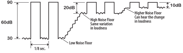 |
Once again I thought we had the explanation nailed for what TubeTraps really did right. And as usual, to some degree, we had, but there was still that nagging issue of cleaning up low end articulation leads to improved treble detail. We still hadn’t figured that part of the equation out. And so for this, let’s turn to the music theory classroom, where the outline for the sound level changes of a single musical event is defined. Where the dynamic nature of a sonic event is defined.
The Life Line of One Sonic Event
What is a sonic event in music? It is the sound level variation of a single musical note. In music theory class a single musical event is defined as an ASRD event, a musical process that has 4 traditionally distinct stages: Attack, Release, Sustain and Decay.A musical line is a sequence of these musical events.
| Typically this describes the lifeline of a plucked or hammered string instrument, a struck percussion or bell instrument and blown wind instruments. In complex music, we have string of rapidly occurring sonic events, such as the rapidly plucked strings of a guitar.
For every attack transient, there is a complex set of harmonics involved. Speaking from the Fourier Transform or FFT perspective, as most audio specialists like to talk about, it takes a huge harmonic series in order to create the attack transient, that very fast rise in sound pressure at the onset of a sonic event. |
 |
There is more to attack transients. They are actually not a tone. They are just a very fast rise in pressure, a spike up in sound pressure. At first the speakers, woofer, mids and highs are standing still and suddenly, as if a huge voltage is snapped across the terminals, all speakers instantly jump forward, creating a rapid vertical increase in sound pressure. After the rapid rise in simple pressure from no pressure to loud pressure, other things begin to happen to that sound, a tone appears for a short or long time and then it dies away, quickly or slowly.
Room AcousticsBut it’s the pressure spike, the Attack and the Release that is our present focus, not the afterglow elements, the Sustain and Decay of the sound. When the speakers jump forward, a pressure pulse is created in the front of the listening room, right around the loudspeakers. The pulse from the mids and highs are typically projected forward because of the size of the baffle board of the speaker. But as for the bass part of that pulse, what the 500 watt power dump into the woofer is doing, the instantaneous pressure pulse snaps out from the speaker with equal strength in all directions. |
 |
Now a third of this pulse snaps away in the front/back direction, a third in the lateral or left/right direction and the other third of the energy snaps in a vertical, up down direction. This means a third of the energy output in generally headed in the right direction, towards the listener and it also means that two-thirds of the speaker’s energy is headed in the wrong direction, exactly perpendicular to the front back direction.
| The direct part of the wavefront snaps toward the listener at the speed of sound. The other 2/3rds of the wavefront snaps also at the speed of sound but in all directions perpendicular to the front back dimension. What happens to this powerful perpendicular shock wave? It gets trapped up in the front of the room. Bouncing back and forth, careening around all 4 surfaces, the two side walls, the floor and ceiling up in the front of the room. I have nicknamed this effect “head end ringing”. | 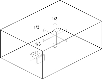 |
| While the remnants of the huge pressure spike are still bouncing around up in the front end of the room, the multiply reflected, and now scrambled sound begins to expand naturally into the rest of the room, down the room at about 1/10th the speed of sound, about 120 feet per second oozing right towards the listener. After about 1/12 second the head end ringing noise begins to significantly engulf the listener with a rising chaos of sound that sounds just like the direct sound the listener just heard except it is arriving a little later and except that the evolution over time of the various frequency components are completely scrambled up. |  |
Sound Masking
The best sound masking sound is a sound that sounds just like the sound that it is supposed to mask, except that the masking sound is a time and phase scrambled version of the original sound. The worst masking sound sounds nothing like the sound that is supposed to be masked. How loud would a hiss sound have to be to mask the staccato tonal presence of a rapidly plucked bass guitar? Probably 40 dB louder than the guitar. If the guitar is being played at 50 dB,A and a steam pipe hiss is kicked on at about 90 dB,A, maybe, just maybe most of the guitar sound would be drowned out. But if the reverberant sound of the guitar itself was used along with a wild set of time delayed attack transients mixed back in, we could mask out the guitar with a sound masking sound level that equals the guitar level alone. Post masking is the psychoacoustic process of listening to a direct sound which is quickly followed by a sound masking type of sound. In this case the head end ringing is post masking the direct signal.
| Let’s look at the statistical version of music. There are 8 separate sound bursts per second, which means each burst lasts 1/16 second and it is followed by 1/16 second of silence, in a perfect world. The head end ringing energy from the leading edge of the former attack transient begins arriving at the listener’s position 1/12th second after the leading edge is heard, which is slightly after the tone burst turns off, Secondly, that same head end ringing is arriving at the listener at just about the same time that the next attack transient begins to arrive. The scrambled version of the leading edge of the first attack transient begins to arrive after 1/12 second after the beginning of the direct signal 1/16th second tone burst. That means the scrambled part of that tone burst begins to arrive just after the end of the direct tone burst, and it proceeds to fill in this subsequent silent 1/16th second time period in the tone burst sequence. |  |
 |
There is another aspect of attack transients we need to take a look at. It’s about listening to music and understanding what we are hearing. Each sound of music can be outlined by the ARSD pattern. When people in general listen to music they listen to the sequence of sustains. But when audiophiles and recording engineers listen, people heavily vested into the sound of the sound they are hearing, they naturally or through training learn to focus on and hear the sound of the attack transient. The truth of the sound is in the sound of the attack transient part of the sound, not in the sustain.
This is born out through psychoacoustic testing. The fundamentals and upper partials of an attack transient define the coloration of the tone of an instrument. Yet, some instruments can have exactly the same set of overtones and sound the same during the sustain but still sound different when their sound includes the attack transient. Tests have been done where the upper partials of an instrument are electronically time delayed, changing the relative phase of the fundamental to the upper partials. There is but only a slight recognition of the changes being made. However if the changes are made before each sound is struck, which includes the attack transient, the relative shifts if upper partial waveform timing are readily noticed. It was only when the phase alignment of the upper partials were included in the attack transient that synthesized musical notes began to sound real.
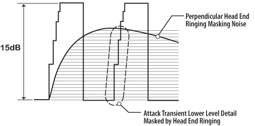
The real program material is delivering 15 db of dynamic range but with head end ringing being uncontrolled, the dynamic range is reduced to only 4 dB. Music suffers from a lack of dynamics because of the masking effect due to head end ringing. The music sounds as if it is compressed with a limiter. Secondly, is that we lost the ability to hear the lower 11 dB of the audible attack transient. We’ve lost the ability to hear more of the attack transient because lingering sound from head end ringing has back filled into the short period of electronic silence that actually is in the original music track. Not being able to hear more low level detain in the attack transient limits our ability to perceive upper partial musical detail.
But Why TubeTraps?
And so, finally we have discovered the connection between adding TubeTraps into the front of the listening room and how the treble range clarity is improved, and along with it, musicality, dynamics, imaging and sound staging. It is about sound masking. When we add TubeTraps to the front of the room, we dry up the build-up and storage of perpendicular sound, head end ringing, as it is being created, and as well, during the quiet time between each tone burst.
| One might be tempted to say that when TubeTraps are cleaning up head end ringing, they are fixing the room acoustic problem before it was even heard. This is unlike RT 60 adjustments in traditional room acoustic work. Here, the problem has already taken place and all that is being done is to more quickly get rid of the bad sound, which has already been created and listened to. |  |
And finally, we look at the TubeTraps themselves: The things that are doing this work. We need to absorb as much vibration out the head end ringing while it is being created as possible. For this we need the most aggressive sound absorption possible. We have very little time to knock down the level of head end ringing, we’d like to reduce it by 10 dB in at least 1/16th second. This corresponds to a RT60 of 0.3 seconds in the deep bass range in the front of the room compared to 1.2 seconds RT60, later when the whole room dies down.
There is only so much room in the front of the room. TubeTraps are very volumetric aggressive, they provide more absorption per cubic foot of bass trap volume than any other bass trap built. TubeTraps out-perform all other bass traps while taking up less space in the front of the room. Pressure zones are not huge and bass traps don’t work outside of these pressure zones. A 50 Hz pressure zone fills the volume out some 2 feet from the wall. Small, highly efficient bass traps are needed to fit nicely inside bass range pressure zones.
Extending Intelligibility into the Subwoofer Range
It didn’t take long after we began to acoustically outfit whole rooms that we realized that sound absorption and diffusion was simply not enough to make good sounding rooms. At some point in each project we reached a limit beyond which no further improvements in the sound of the room could be made. If we had a large plate glass window between the two main speakers, it vibrated thunder regardless how many TubeTraps were put in front of the window. We could turn the volume down and the window thunder didn’t kick up nearly as bad.
Same thing went for the walls and ceiling, only this time it was the subwoofers that were generating the pressure pulses so powerful that they shook the walls and ceiling of the listening room. Simply put, good acoustics just couldn’t eliminate enough of the pressure that pushes the walls and ceiling around. Structural vibration is a completely separate system of room acoustics that needs to be controlled. And it is easily seen in the low frequency end of MATT musical intelligibility curves.
Wall ShudderThis leads us into a whole new world or listening room control, structural shudder control. When a pressure spike hits a wall or ceiling it delivers a short solid blow to the surface. This vibrational surface twangs back and forth with its own resonant tone. These mechanical reverb times are long, easily over 1.2 seconds. The walls and ceiling of most rooms vibrate too freely to be used for any kind of powerful audio in music listening rooms. Explosive transients in an unconditioned room are not tight and clean, they stimulate structural vibration which creates new sounds that are heard but which are not in the program material. |
 |
A sonic boom delivers a huge transient pressure pulse to the roof of a house and when we are inside the house we hear what we think is a sonic boom. However if we were outside in the open, we’d hear something different, the real sonic boom. These two sounds come from the same source but sound very different. What we are really hearing when inside a house starts with the sonic boom but then we have to listen to the after shudder of the house as it calms down from being hit by a fast velvet hammer from the sky. Acoustic testing shows that the sound of a sonic boom is twice as loud inside a house than outside. The noise level inside is really 10 dB stronger inside than outside. This extra 10 dB comes from the sound generated by the extended structural shaking of the structure of the house. Loudspeakers shake houses too.
| Let’s take a wall, 8 x 15’ in size. The edges of the wall are attached rigidly to the corners of the room. But the middle area of the wall is free to move in and out under pressure. Assume the area of this moving part of the wall is 5’ x 10’ = 50 square feet or 7200 square inches. Let’s assume the wall barely quivers, shaking no more than with an amplitude of 1/32 inch back and forth. It displaces 225 cubic inches of air with each movement. |  |
Let’s also look at the displacement of a big subwoofer. If it is 15” in diameter it’s cross sectional area is 182 sq inches. If its throw is 1.25” its displacement is also just about 225 cubic inches. When this sub is displacing that much air we know it is making loud sound. But when the wall quivers, we didn’t even think about it. The best way to imagine what contractor grade flexible walls behave like in high power audio rooms is to imagine a big subwoofer installed in the middle of each wall and a bigger one in the ceiling. There is one real sub in the room that is getting the audio signal. Imagine that this signal is split and run into 5 different reverb circuits. The output of each is amplified to the same power level as the real woofer and fed to the 5 in-wall subs. And now you settle down and light off your system and imagine you are listening to great music.
This pretty much describes the reality of listening to high power audio in normal houses. Not only does the sub shake the surface of the room, but since the surface is connected to the rest of the house, it shakes the rest of the house, and usually the walls of the neighbor’s house. My focus was always to deliver great sound to the listener. Yes, making and selling products was important because it kept the company doors open, but the real goal was not about selling product, it was about making great rooms, rooms that really worked. This wall shaking problem had become the next sound barrier to good sound. It simply had to be dealt with.
| Before we address this, let’s look at the alternative, a room without shaking walls. This might be a concrete room, similar to what is common for residential construction in Europe and Asia. If we have a room whose walls don’t shake, we have in effect, a racquetball court. The sound in this type of room is just about as bad as it is in a reverb chamber. Since the walls don’t flex, all the sound dumped into the room stays in the room. |  |
The only way to get rid of it is to absorb it, using lots of giant bass traps. Personally, I’ve never achieved satisfactory success using acoustics to convert a dedicated, sealed concrete room into a high performance listening room, and I’ve tried…. However, concrete rooms that are typically residential are not so impossible to set up and get sounding good because some of the bas buildup is leaked out of the room through openings, such as windows and lightweight doors, open doorways, halls, stairs and even closets. However, there is one big exception, which we’ll soon cover.
Constrained Layer Damping Construction
Back to wall shudder. Stick frame constructed walls, floors and ceilings comprise the bulk of how listening rooms and home recording studios are constructed. Sheetrock is heavy and studs are stiff and this combination of weight and stiffness results in wall twang, a natural resonant frequency, which is easily stimulated by the subwoofer. The critical listener hears the direct sound accompanied by various arrangements of room acoustics and structural shudder. We had calmed room acoustics but now needed to put the brakes on the sympathetic shudder of the surfaces of the playback room and for that we turned to the world of CLD, constrained layer damping.
Constrained layer damping was not and still isn’t typically usually used in residential or commercial construction but it is commonly used in the construction of ships, boats, trains, planes and RVs. All these vehicles experience severe structural vibration issues, caused usually by their prime motors, and they all need to provide a calm and comfortable ride for the paying passengers. These vehicles are not grounded and the vibration has no opportunity to be resisted by the mass of the ground. Their only solution to runaway vibration is constrained layer damping. We applied this type of construction technique in the DIY type audiophile listening rooms and recording studio projects we were working on and were very pleased to discover how well it worked.
We researched and found an excellent viscoelastic constrained layer damping material used in the manufacturing sector, acquired exclusive rights to process and sell it in the public domain, and we named it ASC-WallDamp. This was back in 1987 and remains still so today. WallDamp is a 1mm thick sheet of damping compound covered with self stick adhesive and release paper. In basic wall construction projects you apply WD Strips to the face of the studs and wall plates and then screw the sheetrock down. The first benefit you hear is that the sheetrock stops vibrating between the stud. That familiar hollow sheetrock sound you hear when you knock on the wall with your knuckle, goes away.
| The second benefit you hear is that the lower frequency shudder from the sheetrock/stud vibration also goes away. It’s thatthumm sound you hear when you double up your fist and thump the middle of the wall, halfway up from the floor. WallDamp strips applied to the face of the stud, blocking and upper and lower plates makes all the difference between noisy walls and calm walls. And don’t forget, while that damping compound is calming the walls, it’s also turning the walls into giant CLD membrane bass traps which absorbs deep bass out of the room. |  |
| If a second layer of sheetrock is applied over the first layer, add WallDamp squares on 9 to 12” centers and WD Strips around the perimeter to the face of the first layer of sheetrock. Screw the second layer of sheetrock down normally. The result is an even more calm walls, floor and ceiling which means we are helping people make better sounding rooms, long before they ever put sound panels or bass traps into the rooms. | 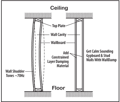 |
ASC IsoDamp Musical Wall System
Calming wall twang down was a good step in the right direction but the frequency of damped wall vibration still depended on what kind of wall the contractor had built. We needed to get rid of the damped wall/stud frequency all together and so we added very flexible metal springs called RC (resilient channel) between the studs and the double layer damped sheetrock to both sides and the damped wall-shudder completely disappeared. By now it was around 1988 and we called this trick wall our “MusicalWall” because the rooms sounded so great when they played music.
| Later we dropped the romantic aspect and just called it our IsoDamp wall system. It is how the walls and ceiling of the 2C3D Reference Rooms were and are still built. We had it tested and it produces STC 51, which is pretty good soundproof rating for a single stud wall, but the main reason for this wall design was because it let high power audio play music as loud as anyone could want.
All audiophiles know how loud they can play their room. It might be around 75 dB,A, or maybe 80 or even 85 dB,A. But whatever it was, you just can’t play the room any harder without it falling apart. Here we have an interesting limit in audio. No sense buying high power audio if your room can’t handle the power. What this limit is about is friction. |
 |
Everything has inherent friction, which is why things tend to stay put, instead of sliding around all the time. Rooms also have inherent, natural friction. As long as you don’t put more power into the room than the room can naturally dissipate, you are playing in a stable environment. However, every room has its threshold, above which, the room cannot dissipate any more power, and when that happens, the room transforms into a vibrating, quaking, thundering twanging badly built giant guitar box.
The room will “break-up” just like a loudspeaker cone will break-up. This is the reason for sound level limits in listening rooms. But, when the room is built like the ASC IsoDamp Musical Wall System, there literally is no limit as to how loud you can play the room. These trick walls and ceiling can handle any pressure which means there is no upper limit as to how powerful your speakers, cables and amps can be. It’s amazing to watch our clients build good rooms and then decide to upgrade their entire electronic chain because now they finally have a place that can actually play high power audio.
Giant Membrane Bass Traps
Instead of flexible walls and ceiling transmitting bass out of the room to get rid of it, we had flexible damped walls and ceiling that absorbed the bass out of the room to get rid of it. The walls and ceiling had become the “damped limp mass” surfaces of a giant membrane bass trap, the walls and ceiling of the room. We knew walls had to flex in the deep bass range, subwoofer range, to remove excess deep bass energy from the room. But in the woofer range of bass, the walls didn’t need to flex to dump energy, because the room acoustic package was handling it.
We experimented and determined that the cross over frequency for the walls and ceiling work best if set at about 50 Hz. That means the suspended wall and ceiling surface needs to weighs around 4#/sqft, which happens to be about 2 layers of sheetrock plus WallDamp. The 4#/sqft surface weight acts like an acoustic cross over. Above 50 Hz it has too much inertia and cannot be moved. Below 50 Hz, the surface is can be moved by the sound pressure.
| The damping factor inside this wall sandwich absorbs low frequency energy fast enough to give the room a reverb time of about 1.2 seconds in the lowest frequency range, which is what it is supposed to sound like. | 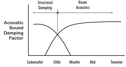 |
| The air cavity inside the wall determines what very low frequency the wall begins to harden up again. Depending on the type of speaker, how many subs and where determines how the air cavity behind the wall varies in depth. |  |
| This finally brings up back to the all-concrete room. What is great about the all-concrete room is that it is sealed from outside noise and holds inside noise inside, which means no one is bothered by what is going on in or outside of the room. We take the concrete room and build a damped flex wall and ceiling inside of it, controlling the air cavity depth behind so the right amount of deep bass wall hardening takes place in the right parts of the room. Finally (1990) we were making great sounding full bandwidth listening rooms. And because these rooms are so well controlled, sound containing and sound attenuating, they also end up being pretty soundproof, especially in the bottom end where soundproofing is usually the weakest, even though the evolution of these rooms was exclusively dedicated to full bandwidth sound conditioning of the listening room. |  |
For a long time we kept trying to get the level of low frequency soundproofing you get with thick concrete using variations of the damped limp-mass idea, the stud/sheetrock/WallDamp part of the IsoDamp wall system. It worked pretty well but when push came to shove, it just wimped out, every time. For a long time I could not figure out how to build real bass proof rooms using a carpenter square, screw gun and wood. I gave up on the mass law and went back to the original soundproofing equation and there it was, staring me in the face, all the time. It is the strength or stiffness part of the soundproofing equation. And now we can build extremely bass-proof walls and ceilings, all out of wood….but how we got there and what we do will have to wait. It’s a whole new story, for another time…
The end of this story goes something like ….After building his audiophile listening room inside a concrete bunker, using the ASC IsoDamp Musical Wall System, our client calls up and says….” Hi Art, just finished with paint and carpet in the new listening room. Don’t worry, everything’s fine. However, I couldn’t stand waiting for the TubeTraps to get here so I rolled the gear in and lit it off anyway….. and wow….It sounds so good…. I think I have to cancel my TubeTrap order….(silence)…” and then he says “…just kidding…. but still…. this empty room sounds so totally good, I can’t imagine how it could ever sound any better, but I know it will, when the TubeTraps get here.” True story, and it happened enough times that I had to believe what they were hearing was true.
And so we see how history repeats itself, only this time, one octave lower. What worked acoustically in the listening room above 50 Hz, years before, using TubeTraps to control the room’s interaction with the sound from the woofer, resulting in more reveal of the attack transient, also worked in the listening room below 50 Hz, where our flexible damped wall system controls the structure of the room to even further reveal more of the attack transient detail.
Conclusion
We started with a few TubeTraps in the corners behind the speakers and that pointed us in the right direction. We ended up building and furnishing full bandwidth listening rooms. But the direction of our evolution was not market driven, or fad driven. A lot of the time we didn’t really know what we were doing, except that it really worked, and we always kept going in the same direction.
What we were doing was developing and defining the art and science of musically intelligible listening rooms. It was fully realized in the deployment of the manufacturer’s choice, the 2C3D reference listening room. Its name meant that it was a 2 channel, 3 dimensional sonic listening environment. It was so 3 dimensional that it was actually an immersion holographic experience. It also proclaimed that, from the perspective of the audio equipment manufacturers:
The Audio System = The Electronic Package + The Room Acoustic.
Along the way, we also figured out how to measure what we were doing which finally lead to our understanding of what we were doing right all along. We started by futilely measuring RT60’s and frequency response curves and ended up developing MATT, the Musical Articulation Test Tones, the definitive testing system for audio playback from the listener’s perspective. It was musical intelligibility all along that drove the evolution of the MATT test and our ability to use it to analyze listening rooms.
Thank you for taking a peek into the world of audio according to Acoustic Sciences Corporation.
